- All
- Product Name
- Product Keyword
- Product Model
- Product Summary
- Product Description
- Multi Field Search

Views: 2643 Author: Site Editor Publish Time: 2020-04-02 Origin: Site
Cable Mechanical Configuration and Material Requirements
High-/full-speed and low-speed cables differ in data conductor arrangement and shielding. Low-speed recommends, but does not require, use of a cable with twisted data conductors. Low speed recommends,but does not require, use of a cable with a braided outer shield.
Below shows the typical high-/full-speed cable(USB 2.0) & Super high speed cable(USB 3.0)construction.


Description
High-/full-speed cable consists of one 28 to 20 AWG non-twisted power pair and one 28 AWG twisted data pair with an aluminum metallized polyester inner shield, 28 AWG stranded tinned copper drain wire,> 65% tinned copper wire interwoven (braided) outer shield, and PVC outer jacket.
Low-speed cable consists of one 28 to 20 AWG non-twisted power pair and one 28 AWG data pair (a twistis recommended) with an aluminum metallized polyester inner shield, 28 AWG stranded tinned copperdrain wire and PVC outer jacket. A > 65% tinned copper wire interwoven (braided) outer shield is recommended.
Construction
Raw materials used in the fabrication of this cable must be of such quality that the fabricated cable is capable of meeting or exceeding the mechanical and electrical performance criteria of the most current USB Specification revision and all applicable domestic and international safety/testing agency requirements; e.g., UL, CSA, BSA, NEC, etc., for electronic signaling and power distribution cables in its category.
Table- -Power pair
American Wire Gauge(AWG) | Nominal Conductor Diameter | Stranded Tinned Conductors |
28 | 0.381 mm (0.015”) | 7x36 |
0.406 mm (0.016”) | 19x40 | |
26 | 0.483 mm (0.019”) | 7x34 |
0.508 mm (0.020”) | 19x38 | |
24 | 0.610 mm (0.024”) | 7x32 |
0.610 mm (0.024”) | 19x36 | |
22 | 0.762 mm (0.030”) | 7x30 |
0.787 mm (0.031”) | 19x34 | |
20 | 0.890 mm (0.035”) | 7x28 |
0.931 mm (0.037”) | 19x32 |
Note: Minimum conductor construction must be stranded tinned copper.
Non-Twisted Power Pair:
A.Wire Gauge: Minimum 28 AWG or as specified by the user contingent upon the specified cablelength. Refer to Table--Power pair.
B.Wire Insulation: Semirigid polyvinyl chloride (PVC).
1.Nominal Insulation Wall Thickness: 0.25 mm (0.010”)
2.Typical Power (VBUS) Conductor: Red Insulation
3.Typical Ground Conductor: Black Insulation
Signal Pair:
A.Wire Gauge: 28 AWG minimum. Refer to Table--signal pair
Table--signal pair
American Wire Gauge(AWG) | Nominal Conductor Diameter | Stranded Tinned Conductors |
28 | 0.381 mm (0.015”) | 7x36 |
0.406 mm (0.016”) | 19x40 |
Note: Minimum conductor construction must be stranded tinned copper.
B.Wire Insulation: High-density polyethylene (HDPE), alternately foamed polyethylene or foamedpolypropylene
1.Nominal Insulation Wall Thickness: 0.31 mm (0.012”)
2.Typical Data Plus (+) Conductor: Green Insulation
3.Typical Data Minus (-) Conductor: White Insulation
C.Nominal Twist Ratio (not required for low-speed): One full twist every 60 mm (2.36”) to 80 mm(3.15”)
Aluminum Metallized Polyester Inner Shield (required for low-speed):
A.Substrate Material: Polyethylene terephthalate (PET) or equivalent material
B.Metallizing: Vacuum deposited aluminum
C.Assembly:
1.The aluminum metallized side of the inner shield must be positioned facing out to ensuredirect contact with the drain wire.
2.The aluminum metallized inner shield must overlap by approximately one-quarter turn.
Drain Wire (required for low-speed):
A.Wire Gauge: Minimum 28 AWG stranded tinned copper (STC) non-insulated. Refer to Table--Drain Wire Signal Pair
Table--Drain Wire Signal Pair
American Wire Gauge(AWG) | Nominal Conductor Diameter | Stranded Tinned Conductors |
28 | 0.381 mm (0.015”) | 7x36 |
0.406 mm (0.016”) | 19x40 |
Interwoven (Braided) Tinned Copper Wire (ITCW) Outer Shield (recommended but not required for low-speed):
A.Coverage Area: Minimum 65%.
B.Assembly: The interwoven (braided) tinned copper wire outer shield must encase the aluminummetallized PET shielded power and signal pairs and must be in direct contact with the drain wire.
Outer Polyvinyl Chloride (PVC) Jacket:
A.Assembly: The outer PVC jacket must encase the fully shielded power and signal pairs and mustbe in direct contact with the tinned copper outer shield.
B.Nominal Wall Thickness: 0.64 mm (0.025”).
Marking: The cable must be legibly marked using contrasting color permanent ink.
A.Minimum marking information for high-/full-speed cable must include:USB SHIELDED <Gauge/2C + Gauge/2C> UL CM 75 oC — UL Vendor ID.
B.Minimum marking information for low-speed cable shall include:
USB specific marking is not required for low-speed cable.
Nominal Fabricated Cable Outer Diameter:This is a nominal value and may vary slightly from manufacturer to manufacturer as a function of theconductor insulating materials and conductor specified. Refer to Table--Nominal Cable Diameter
Table--Nominal Cable Diameter
Shielded USB cable configuration | Nominal outer cable diameter |
28/28 | 4.06 mm (0.160”) |
28/26 | 4.32 mm (0.170”) |
28/24 | 4.57 mm (0.180”) |
28/22 | 4.83 mm (0.190”) |
28/20 | 5.21 mm (0.205”) |
USB cable manufacturing process:
Conductor Bunching→Conductor Insulating→Pair twisting+Alu foil screening→Multicore cabling+Alu foil screening→Braiding→Outer jacket sheathing
Equipment required to produce USB cable
TZ-BM300/500 double twisting bunching machine→For power pair & signal pair conductors bunching
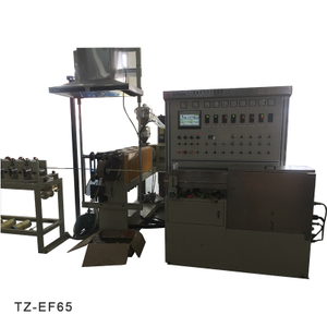
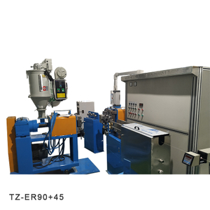
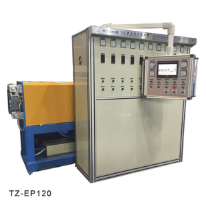
TZ-EP50 extruder machine production line→For bunched conductors insulating of PVC
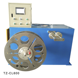
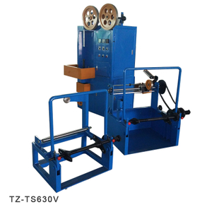
TZ-SC500 cantilever single twisting machine→For Pair twisting+Alu foil screening
TZ-SC630 cantilever single twisting machine→For Multicore cabling+Alu foil screening+drain wire filling
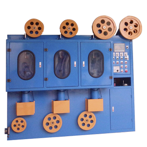
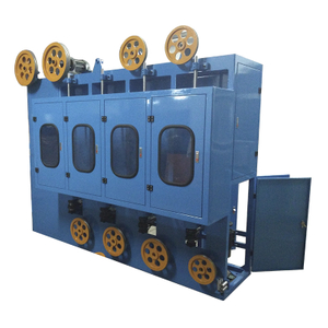
16 courier braiding machine→For Braiding by tinned copper wire
TZ-EP70 extruder machine production line→For Outer jacket sheathing of PVC
TZ-ES65 silicone cable extruder line→For Outer jacket sheathing of Silicone(USB 3.1)
16 courier braiding machine→For Outer Braiding by fiber yarn
Taizheng Machines: